|
There is no "one fits all" solution.
The way how Boxy Cat is designed and built is based on a number of requirements.
Legal Requirements
Currently the regulations in Vietnam seem to be:
Up to 05 HP: only the certificate of participation in a short course is required.
Up to 15 HP: a boat driver's license is required. That seems to be equivalent to a car driver's license.
All boats and ships with larger engines need a licensed captain and engineer.
The necessary patents are only available from professional full-time schools and colleges.
Therefore, for practical reasons, any private boat should need no more than 15 HP engine power.
Transport Requirements
There are no car trailers in Vietnam. Larger lorries are severely restricted and cannot move inside town.
The only viable transport option as of 2007/08 is therefore:
Car's roof rack: not many cars have one, but it should be available for serious boating.
Vans: See this page for details.
Basically, the max. foot print of any load is a bit over 3 m x 1.7 m, with a bit more than 2 m height.
(or 10' x 5.5' x 8'). For exceptions a bit more .... taking a larger truck.
Material Requirements
Easily available: Indoor-quality ply, lumberyard wood, 0.7-mm zinc galvanized sheet metal, white styrofoam
More difficult available: Outdoor-quality ply (according to present information only for 10mm up (3/8"),
and only if ordered in larger batches)
Not available: Marine grade ply.
Building Space and Time Requirements
Optimal: Enclosed and exclusive workshop, at ground level, like in our Thai Ha Yard.
Not good: Open, shared worspace, at roof terrasse, like in our Kim Ma Thuong Yard.
See our "Yard Page" for details.
Very poor: tiny workspace, like in our present Dao Tan Yard.
Means: No operations that make major dust like much sawing, planing, and especially sanding.
No operations that need to take place over a fixed time, like adding layers of epoxy or paint
before the previous one is fully cured.
Suitable operations therefore:
Cutting, bending (near to edge), soldering sheet metal.
Limited sawing of wood. Glueing, screwing.
The Solutions
Build Modules that can be built even in very limited building space, can be transported easily,
and allow usage of the boat, even if it is not yet completely finished.
Separate Floats and Superstructure. Only the floats need to be watertight.
The superstructure only needs to be rain proof. Since we build only for very protected waters, this is feasible.
The superstructure can therefore be built in flat panels, that get assembled only on the water,
like the walls of a ready-made/pre-built house.
Use zinc coated sheet metal as the main material for the floats, and ply (if necessary even indoor-quality)
for the superstructure.
The cross section of the floats could thus look like this:
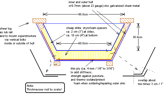
Except for the bevel at the inner sheer log (planed or ripped), no production step makes much noise,
or creates much dust. The layers would be fixed by glueing with Epoxy.
Repair of the outer skin, if necessary later on, is easy: Just disconnect the module from the boat,
sand off the paint, solder a patch of sheet metal, re-paint, and connect the module again.
The sketch above shows version 2. Version 1 had vertical sides of 1' height, and bent corners at the bottom,
allowing it to be made from 4' wide sheet metal. The slanted sides give a flair that looks better,
behaves better (increases reserve bouancy),
increases the volume, thus displacement by about 20%, while decreasing the draft by about 10%.
The disadvantage of long bends far from the edge (1' in version 1) is that they are difficult to do
without large folding presses, i.e. not very suited for "backyard building".
Therefore version 2 replaces the bends with soldered connections, where the bend is only an inch from the edge,
therefore easy to be done with hand tools. The solder connection needs some overlap of the sheets.
The drawback of this is that it is not possible anymore to get the whole cross-section from a single 4' sheet.
Instead, the sides are cut as 4/3' (i.e. three side panels from one 4' sheet).
Deducting the required overlap, this is still more than the original 1' wide sheet, increasing the displacement again.
A nice side benefit of the overlap is that it strengthens the chine bend.
The drawback of the slanted sides is, that the modules cannot be mounted "side by side" anymore to create a wide float.
Another drawback is that the weight of the superstructure will result also in a force component
that tries to bend the sides outwards. Since part of the upper walls are also planned to be in sandwich construction,
the weight of the superstructure should not be much, but in case it turns out that it is too much for the sheer logs
and the sandwich of the float's sides, then there need to be cross beams, and/or decks that are bolted to both sheer logs,
and prevent them to bend outwards, or - the best solution - place the weight of the superstructure not onto the sheer logs,
but via columns down to the inside bottom of the floats, where it would be distributed along the length and width via a grid
of loosely placed stringers and frames.
The floats would be made of 8-feet long straight modules, and bow modules at front.
The bow modules might have a punt form or might be pointed, with or without rocker.
An 8-feet long straight module displaces about 240 kg (530 lbs) at 0.5' draft.
The maximum design displacement would be around 540 kg (1200 lbs) at 1' draft.
In case of overloading, at 1.33' draft, the sheer of the floats would be at water level,
i.e. the connecting bottom panels would start to become part of the hull.
The displacement at that point is 770 kg (1700 lbs).
With on average of not much more than one passenger per float in cruise mode that displacement capacity should be ample.
|