How to Use FREE!ship
- an unofficial tutorial -
Part 4: Forming the Hull - Z Axis
First we'll do the forward half of the boat. Since the aft part only disturbs us, we'll hide those layers: Sides Aft, Bilge Aft, Bottom Aft, View Aft. We do that by unchecking the box in front of their names in the layer dialog. We get it with the  button.
What we know from the Bow view are the coordinates at X=9 and at the stem. So we select the point at X=9 at the sheer and set Z=0-24 (i.e. the point is now 9,3,2). We select the point at X=9 at the lower edge of the side panel and set Z=0-9. The points at X=9 at both sides of the bottom panel will be at Z=0. From the Bow view we know also the width of the bottom at X=9: We set the outer point of the bottom panel to Y=0-24. Hey, we have now completely defined the cross section at the max. beam!
Now let's look at the stem. We select the top, frontmost point, at X=20, and set it to Z=0-36. The point below we set to Z=0-30, and the frontmost point of the bottom panel (at X=18) to Z=0-6.
Now let's have a look at the Bodyplan view. I have selected the sheer line, so it appears as yellow:
The sheer is strangely bent, while in fact it should be a straight line in Bodyplan view. The points at the max. beam and the stem are correct already, but the points between are too low. So we'll select now one point of the sheer line after the other and set the Z coordinate by trial and error until it lies on top of the straight line. To make it easier, and more exact, we'll zoom in the Bodyplan view. After setting the points, I have selected all of them, and this is how it looks now:
We can do the same now for the bottom edge of the side panels:
However, we can't use the same procedure for the bottom panel, since the Z coordinates of it are not yet determined. For the forward half of the hull, where the Bilge panel is twisted, Jim takes the measurements from a drawing.
I think those values come close: X=10/Y=1.96; X=12/Y=1.75; X=14/Y=1.30; X=16/Y=0.70. We set those values easily by selecting the points in Plan view. Now we can go back to Bodyplan view. We set all those four front sections of the bottom panel by selecting the inside and outside point of each and setting the Z coordinate of them so that the outside point of the bottom panel lies on the straight line:
We are done with the front section! If you haven't saved your work yet, this would be a good time to do it.
Let's work on the aft half.
Open the Layer Dialog, unhide the aft layers, and hide the front layers.
Now you know the game: The aft point of the sheer line (X=0, at the bulkhead) goes to Z=0-28 (taken from the Stern View drawing). The point at X=9 is already correct. Now, in Bodyplan view, move the Z coordinates of the other points of the sheer line up, so that the projection is a straight line.
The same with the lower edge of the side panels. The aft point at X=0 goes to Z=0-16.6 - and the other points into a straight line in Bodyplan view.
With the bottom panel we have the same problem like in the forward half: Jim does not give dimensions of the width. We'll try the same graphical approach like he. For that we hide the interior edges  . From the Stern view drawing we know the width of the bottom panel at the transom. We set that point to Y=0-15, and then set the Z value of both aft points (at X=0) to Z=0-9. When moving the four points onto the straight line, this time we will not only change the vertical Z coordinates, but also the Y coordinates in such a way that the lines that connect them with the upper edge of the Bilge panel (see the yellow lines below) are all in parallel with the red line that defines the max. beam of the Bilge panel.
This is a good time to move the points with the cursor, then do the fine adjustment with the dialog box.
Finally we have to make the bottom panel flat by moving the points at the center to the same Z coordinate like the corresponding points at the chine. The lines at the bottom panel should be then horizontal:
We are done - nearly. Our boat has no transom yet.
You know already some ways how to do it: We could select the points at the end of the panels and make a new face to connect them with  . This is what we would get:
Just insert one point in the diagonale by splitting this edge  and move it to its final point at 0,0,0-28.
Then set the points as Corner points, and the edges around the transom as Crease edges
 .
.
Alternatively, you could create a new point, set it to 0,0,0-28 and then create a new face with all the points around the transom.
But I want to show you another way, using one more feature. In case you followed the instructions above and therefore have already a transom, I suggest that you do repeated "Edit -> Undo" until the transom is gone again.
We select the vertical aft edge of the side panels.
In Perspecive view make sure that you selected the edge of the side panel, not that one of the projection!.
Then we choose from the menu Edge -> Extrude, or - more easy - just click the corresponding button  . We get a dialog
where we set the direction of the extrusion. We want the new face to go inward from the selected edge, i.e. from Y=2 feet (24 inches) to Y=0 feet. So we enter -2, or -0-24 and click the OK button.
We have the upper part of the transom. Now select the four corner points of the lower part and create a new face
. We know the rest: set edges to Crease edges, and make points to Corner points. Finally make the inside edges visible , select the new faces
and assign them to the "Transom" layer 
Finished! You know by now pretty much all features that you need to edit a hull. Wait - I forgot to mention one issue: Every edge can belong only to one or two faces, not to more. If your design would require a third face connected to one edge, then you'll need to find ways around it, e.g. by running a face in close distance parallel to an existing face. I'll show you that in part 6.
The rest of our design is clean-up work: Make all layers visible. Select all points or edges of the projections in front of the bow and aft of the transom and delete them via the menu Edit -> Delete, or - more easy - just click the corresponding button  . Then select the aft halfs of the panels and assign them back to the original layer. Finally delete all empty layers. Either via the menu Layer -> Delete empty, or - more easy - just click the corresponding button
  . This button is also available in the Layer Properties dialog.
Finally we want to see our Bobsboat a bit more nicely. In any or all of the four views we do a right-click and select "Mode -> Shade". Looks nice, just the control net still disturbs us. So let's get rid off it. Menu Visibility -> Control net, or - more easy - just click the corresponding button  .
.
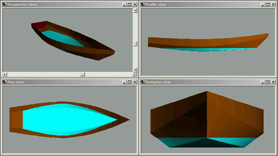
How does it look like?
Looks like Jim Michalak's Bobsboat to me.
In part 5 we'll look at all the amazing outputs that FREE!ship provides.
---
Oops, looks like the author of this tutorial didn't finish his job ;)
That 5th part was planned but never written.
Actually, I think it is not necessary.
You should have by now the basics to use FREE!ship and to play with it.
Furthermore, since FREE!ship is still in active development,
it would need a permanent editing of this tutorial to keep it up-to-date.
The trick with the dummy layers is e.g. not needed anymore in the current version.
Just load the drawing as a background image.
If somebody wants to continue where the editor stopped, pls. feel free to contact me
at stefan.probst(at)opticom.v-nam.net.
I think I can convince the author (he shares the name and an eMail address with me, after all)
to link to a continuation, or to include that continuation in this tutorial.
Since he is busy playing with FREE!ship (his latest model has more than 1700 faces,
close to 3900 edges, and nearly 2200 points), I don't expect that he will continue on his own.